Volume Rendering
Based on a series of images of the same volume, it is possible to view the volume in different visualizations based on Volume Rendering.
• MPR: Multi Planar Reconstruction
• 3D: 3-Dimensional rendering
To enable or disable this optional feature, please contact Dedalus support.
|
Warning |
|

|
The accuracy of the calculated Volume Rendering images depends on the quality, pixel spacing, and slice spacing (relative image position for each image in the series) of the original images. Depending on the view (zoom, chosen slice thickness, render mode, orientation, ... ), gaps between the original pixels might be calculated into newly displayed pixels, and/or single pixels could be a recalculation of multiple original pixels. The user should always be aware of this and verify any data and findings in the Volume Rendering images with the original series, before making any medical decisions or diagnosis.
|
|
Note |
|

|
These functionalities are not supported on mobile devices.
|
Volume Rendering and other reconstructions or renderings are available only for image series that meet the following requirements:
• Modality types: CT, MR
• Number of images: 10 or more
• Image orientation: Images must have the same orientation
• Image type: Monochrome
• Bit depth: No 8-bit images
Available views
Viewports that support Volume Rendering will have the 3D (Volume Rendering) button in the toolbar which can be activated in any of the available views:
• 2x2: Displays an axial, coronal, sagittal, and 3D view in 4 viewports.
• Triplane: Displays an axial, coronal and sagittal MPR view in 3 viewports.
• Coronal
• Axial
• Sagittal
• 3D
You can switch between the views using the 3D button in the toolbar or the context menu (right mouse click) under View.
In each of the views, the overlays are displayed as in the original series.
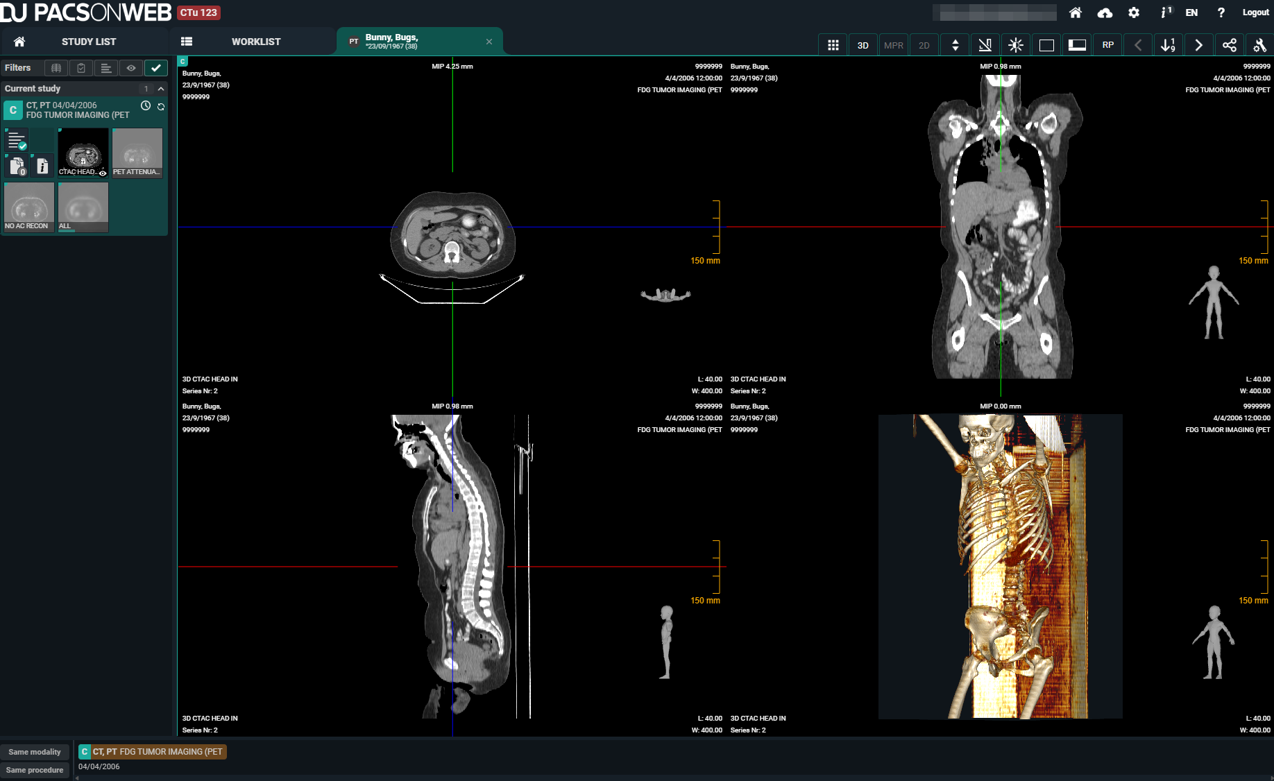
Number | Designation | Description |
|---|---|---|
1 | Patient information | Patient information, such as the patient's name, date of birth, and Patient ID. |
2 | MPR render mode | MPR render mode indicates which render mode and slice thickness applies for that view. Example: MIP 0.89 mm. |
3 | Study information | Study information, such as the procedure and study date. |
4 | Series information | Series information, such as series number. The initial view (sagittal, coronal, axial or 3D) is also displayed. |
5 | Image information | Image information, such as length and width of the image, image number in the series, and zoom level. |
6 | Reference lines | In each of the planes, the intersections with the other MPR planes are displayed as colored interactive reference lines. These reference lines can be used to rotate the views or drag the center-point, and by doing so, navigate through the volume. |
MPR settings
For the MPR views, it is possible to adapt the slice thickness via MPR settings. You can find the MPR settings in the 3D menu or by clicking on the MPR render mode overlay (see Number 2 in table above).
• Set the render mode:
◦ MIP: Displays the maximum intensity projection for each pixel in the volume within the range of the slice thickness (lightest pixels).
◦ MinIP: Displays the minimum intensity projection for each pixel in the volume within the range of the slice thickness (darkest pixels).
◦ AvgIP: Displays the average intensity projection for each pixel in the volume within the range of the slice thickness (average of the pixels).
• Adapt the slice thickness:
When adapting the views, you can move the slider to indicate a target slice thickness. When sliding, the different MPR views will adapt to a slice thickness closest to the target slice thickness.
These may vary depending on the slice thickness, pixel spacing, and slice spacing of the original series in addition to the orientation of the specific view.
3D render modes
You can adapt the 3D Mode to define the way the 3-Dimensional rendering happens. This can be done via the 3D menu.
• MIP
• Default CT
• Bones
• Vessels
• Skull
• Lung
• Soft
Additionally, the Window Level tool can help filter out less or more dense pixels from the volume in the rendering.
3D clipping
With 3D clipping, a reference box can be shown in the MPR views where you can adapt the range of the volume that should be rendered. Pixels outside the defined shapes will be ignored for creating the 3D render.
Tools and actions
You can scroll, zoom, pan, and adapt window level on volume rendering images.
For the MPR views (axial, sagittal, coronal) the zoom level will always be aligned and change simultaneously. The 3D view changes separately.
Currently, it is not possible to perform measurements or add annotations in any of the Volume Rendering views. It is advised to perform these on the original images.